A beam of plane polarized light can be obtained from a Nicol prism. This beam of plane polarized light is made incident normally on the surface of a calcite crystal cut parallel to its optic axis.
As shown in
Fig. 14.32(a), let the plane of polarization of the incident beam make an angle
θ with the optic axis and let the amplitude of this incident light be
A.
As polarized light enters into the calcite crystal, it will split into two components, e-ray and o-ray. The e-ray ...
Energy density of classical electromagnetic waves[edit]
Energy in a plane wave[edit]
Main article:
Energy density![\mathcal{E}_c = \frac{1}{8\pi} \left [ \mathbf{E}^2( \mathbf{r} , t ) + \mathbf{B}^2( \mathbf{r} , t ) \right ] .](https://upload.wikimedia.org/math/9/6/1/961221d79bd5c89dd4535fe407352379.png)
For a plane wave, this becomes

where the energy has been averaged over a wavelength of the wave.
Fraction of energy in each component[edit]
The fraction of energy in the x component of the plane wave is

with a similar expression for the y component resulting in

.
The fraction in both components is

Momentum density of classical electromagnetic waves[edit]

For a sinusoidal plane wave traveling in the z direction, the momentum is in the z direction and is related to the energy density:

The momentum density has been averaged over a wavelength.
Angular momentum density of classical electromagnetic waves[edit]
Electromagnetic waves can have both
orbital and
spin angular momentum.
[1] The total angular momentum density is
![\boldsymbol { \mathcal{L} } = \mathbf{r} \times \boldsymbol { \mathcal{P} } = {1 \over 4\pi c } \mathbf{r} \times \left [ \mathbf{E}( \mathbf{r}, t ) \times \mathbf{B}( \mathbf{r}, t ) \right ].](https://upload.wikimedia.org/math/c/c/3/cc3fd4d6d433079c499dd85c9388b780.png)
For a sinusoidal plane wave propagating along

axis the orbital angular momentum density vanishes. The spin angular momentum density is in the
direction and is given by

where again the density is averaged over a wavelength.
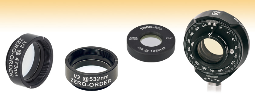
Optical filters and crystals[edit]
Passage of a classical wave through a polaroid filter[edit]
A
linear filter transmits one component of a plane wave and absorbs the perpendicular component. In that case, if the filter is polarized in the x direction, the fraction of energy passing through the filter is

Example of energy conservation: Passage of a classical wave through a birefringent crystal[edit]
An ideal
birefringent crystal transforms the polarization state of an electromagnetic wave without loss of wave energy. Birefringent crystals therefore provide an ideal test bed for examining the conservative transformation of polarization states. Even though this treatment is still purely classical, standard quantum tools such as unitary and Hermitian operators that evolve the state in time naturally emerge.
Initial and final states[edit]
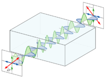
A birefringent crystal is a material that has an
optic axis with the property that the light has a different
index of refraction for light polarized parallel to the axis than it has for light polarized perpendicular to the axis. Light polarized parallel to the axis are called "
extraordinary rays" or "
extraordinary photons", while light polarized perpendicular to the axis are called "
ordinary rays" or "
ordinary photons". If a linearly polarized wave impinges on the crystal, the extraordinary component of the wave will emerge from the crystal with a different phase than the ordinary component. In mathematical language, if the incident wave is linearly polarized at an angle

with respect to the optic axis, the incident state vector can be written

and the state vector for the emerging wave can be written

While the initial state was linearly polarized, the final state is elliptically polarized. The birefringent crystal alters the character of the polarization.
In a beam of electromagnetic radiation the vectors of electric field
E and magnetic field
H are perpendicular to the direction of the light propagation. Because vectors
E and
H of electromagnetic wave are perpendicular also to each other, the state of the light anisotropy in the direction perpendicular to the wave propagation can be described by any of these two vectors. Generally, the polarization direction is the direction of the electric field vector
E.

Light emitted by separate atoms and molecules is always polarized. Nevertheless, any macroscopic source of the light consists of huge number of such separate emitters and the direction of the electric field at any moment of the time is not predictable. Such light is called unpolarized or natural light. Using light polarizer (polarization filter) we can suppress the component of the light polarized in one direction and transmit only the component polarized in perpendicular direction. Behind the polarizer the light will be plane-polarized. In general case, the totally polarized light consists of two perpendicular plane-polarized components. Depending on the amplitude of these two waves and their relative phase, the combined electric vector traces out an ellipse and the wave is said to be elliptically polarized. Elliptical and plane polarization can be converted into each other by means of birefringent optical systems. Animation shows two waves: one of them are linear polarized wave and the other one is the circularly polarized wave. The electric field vector of linearly polarized electromagnetic wave (marked in blue) oscillates only in one direction. In circularly polarized wave the end of electric field vector (marked in red) moves like a coil.
 If the lineally-polarized (plane-polarized) light is incident onto the polarizer, then the intensity of the transmitted light I will depend upon the angle a between the direction of the light polarization and the orientation of the polarizer as follows:
I = I0cos2a
Animation shows the experiment when the Gaussian beam with linear polarization is incident onto the rotating polarizer. As a result the intensity of light spot on the screen behind the polarizer is varied harmonically depending on the angle between the polarization direction and polarizer angle.
Let us consider flat electro-magnetic wave propagating in the positive direction along the axis x. In this case the equation of such a wave can be written as:
 |
Ex = 0, Ey = E0cos(wt - kx), Ez = 0;
Hx = 0, Hy = 0, Hz = H0cos(wt - kx);
|
where k=w/c is the wave constant, c is the velocity of the light. As we can see from the animation there is no oscillation of electric and magnetic components of wave in the direction x (Ex=Hx = 0). This means the the electromagnetic wave is the transverse one. This is one of the principle differences of electromagnetic wave as compared to the wave of mechanical stresses. Another principle of electro-magnetic wave propagation is that the vectors E and H oscillate in phase, i.e. they achieve the maximum value in the same points of the space.
 Ellipsometry is a non-destructive optical technique, which deals with the measurement and interpretation state of polarized light undergoing oblique reflection from a sample surface. Linearly polarized light, when reflected from a surface, will change its state to elliptically polarized because of presence of the thin layer of the boundary surface between two mediums. Dependence between optical constants of a layer and parameters of elliptically polarized light can be found on basis of Fresnel formulas. The green line of mercury lamp or laser beam is used in ellipsometry as a source of light. The wide-band light of incandescent lamp can also be used for spectroscopic measurements. The laser has a higher power which gives a higher signal to noise ratio for better imaging at a wavelength where the sample is transparent. Animation shows two linear polarized waves incident on the surface. The wave, which reflects from a thin film of a sample, becomes circularly polarized wave, while the other wave reflected from a substrate does not change the state of polarization.

 The microscopy with the use of the principles of ellipsometry is shown in the next animation. The beam of light comes out of the laser or lamp (marked in red), then the first polarizer (green) selects an angle for linear polarization, then the 1/4 wave plate compensator (blue) generates the correct elliptically polarized light such that it reflects off the surface linearly, then the analyzer (green) is adjusted to cross with that angle to find a null. As a result the sample becomes visible as a black spot on the white background of substrate, which reflects the light in the same polarization. The image of a sample is detected and recorded with the aid of photodiode matrix. Changing the orientation of the polarizer and analyzer we can achieve the positive picture of the sample, the negative one and all intermediate states. More detail information on imaging ellipsometry can be found on the website of the company


 is incident on the crystal. Let θ denote the angle between
  , where
 lies along the waveplate's slow axis. The effect of the half-wave plate is to introduce a phase shift term eiΓ = eiπ = −1 between thef and s components of the wave, so that upon exiting the crystal the wave is now given by
![E (\cos\theta\, \mathbf{\hat f} - \sin\theta\, \mathbf{\hat s})\mathrm{e}^{i(kz-\omega t)} = E [\cos(-\theta) \mathbf{\hat f} + \sin(-\theta) \mathbf{\hat s}]\mathrm{e}^{i(kz-\omega t)}.](https://upload.wikimedia.org/math/3/1/4/3145409fbe3b284da9098b1b956f793c.png)
 denotes the polarization vector of the wave exiting the waveplate, then this expression shows that the angle between
  . For linearly polarized light, this is equivalent to saying that the effect of the half-wave plate is to rotate the polarization vector through an angle 2θ; however, for elliptically polarized light the half-wave plate also has the effect of inverting the light's