this blog will give information about vlsi for every vlsi students

Wednesday 15 July 2015

DIFFRACTION IN OPTICS OF PHYSICS FOR B-TECH JNTU STUDENTS

DIFFRACTION IN OPTICS

Diffraction refers to various phenomena which occur when a wave encounters an obstacle or a slit. In classical physics, the diffraction phenomenon is described as the interference of waves according to the Huygens–Fresnel principle. These characteristic behaviors are exhibited when a wave encounters an obstacle or a slit that is comparable in size to its wavelength. Similar effects occur when a light wave travels through a medium with a varying refractive index, or when a sound wave travels through a medium with varying acoustic impedance. Diffraction occurs with all waves, including sound waves, water waves, and electromagnetic waves such as visible lightX-raysand radio waves.

The effects of diffraction are often seen in everyday life. The most striking examples of diffraction are those that involve light; for example, the closely spaced tracks on a CD or DVD act as a diffraction grating to form the familiar rainbow pattern seen when looking at a disk. This principle can be extended to engineer a grating with a structure such that it will produce any diffraction pattern desired; the hologram on a credit card is an example. Diffraction in the atmosphere by small particles can cause a bright ring to be visible around a bright light source like the sun or the moon. A shadow of a solid object, using light from a compact source, shows small fringes near its edges. The speckle pattern which is observed when laser light falls on an optically rough surface is also a diffraction phenomenon. When deli meat appears to be iridescent, that is diffraction off the meat fibers.[3] All these effects are a consequence of the fact that light propagates as a wave.

Interference and Diffraction

The terms "interference" and "diffraction" were originally used with the Newtonian corpuscular theory of light, but were taken over to describe the same phenomena in the new wave theory. What is called "interference" refers to the operation of the principle of superposition: the amplitudes in two light fields simply add, but in no way affect each other or "interfere". This is a fundamental property of the Huygens-Fresnel theory of the propagation of light, and appears in every application of it. However, it may be useful to think of "interference" in a restricted sense as involving a countable number of beams (often two) with the characteristic appearance offringes, periodic spatial variations in intensity.
"Diffraction" may refer to all the phenomena observed near shadows, or may be limited to the property of waves to bend around an obstacle. If used in this restricted sense, then the observed fringes are a result of interference of the diffracted waves with others. The apparent absence of diffraction of light was strong evidence against a wave theory. However, diffraction of light was eventually recognized (by Grimaldi, 1665) at a remarkably late date. It was also a prediction of Huygens' wavelet theory, invented to explain double refraction. However, there was no periodicity in Huygens' theory, and no explanation of fringes.
Fresnel combined the periodicity of light discovered by Young with the wavelet idea of Huygens. Each point on a wavefront at a given instant is the source of a spherical wavelet. The sum of the wavelets emitted from all points on the wavefront at an observation point P is the resultant amplitude there, and the intensity is the square of this amplitude. This Huygens-Fresnel principle, published in 1818, is remarkably in accord with observations.
There are several reasons why diffraction phenomena are so difficult to observe that they were not recognized until Grimaldi's time. These are: lack of coherence in the light source; insufficient intensity of the light source; and small size of the pattern. Coherence is the ability to produce interference fringes, demanding stable phase relations both in time and space, called temporal and spatial coherence, respectively. White light, with wavelengths between 400 and 700 nm, can produce fringes only in low orders, as in oil films or Newton's rings. Good temporal coherence demands monochromaticity. The coherence time is roughly the reciprocal of the frequency bandwidth. Spatial coherence means that the fringes will fall at definite locations, not smeared out over the observing screen, as happens with broad sources. They may indeed produce fringes, but they overlap and cannot be seen. The Sun is a bright source of nearly parallel light, but not parallel enough to make diffraction fringes distinct.
Coherence can be provided by using a spectral lamp (sodium, or mercury with a filter) and a pinhole, perhaps preceded by a condensing lens. The disadvantage, however, is a greatly reduced intensity. If the fringes to be viewed are linear, the intensity can be greatly increased by using a slit, oriented parallel to the fringes. At the present time, a laser gives bright coherent light that will exhibit fringes around any shadow. The beam has to be expanded by using a short-focus lens.


Interference and diffraction are the main phenomena which demonstrate the wave nature of the light. There are many optical devices, where these phenomena can be observed. Diffraction grating is one of them, which allows a beam of light to be resolved into different colors. Diffraction grating consists usually of thousands of narrow, closely spaced parallel slits (or grooves). The use of diffraction gratings DG10 and laser pointer allows these effects to be easily demonstrated and investigated at home, school, university, etc. At this website we consider the basic theory of Fraunhofer diffraction at one, double and multiple slit as well as the real experiments with diffraction gratings DG10, Fresnel zone plates FZP-01 and Gabor hologram HH-4000.

If we illuminate diffraction grating with monochromatic light of laser source, then the beam is splited into several divergent beams in accordance with parameters of grating. Particularly the angles between the beams will be inversely proportional to the period of grating. Investigating the interference pattern on the remote screen we can make a conclusion about parameters of grating. And, on the contrary, knowing the parameters of grating we can easily calculate the wavelength of light. The set DG10 contains also single slits and double slits of different width. In the figure below you can see the result of the diffraction of light at a single slit. Such an interferometric method allows the size of the minute objects (sand, dust, powder,..) to be precisely measured.
If the light is not monohromatic, then the angle of  diffraction depends upon the wavelength. In this case the spectrums of radiation in different orders will appear instead of the beams. Let us place the diffraction grating DG-2/1-4000 in front of objective glass of photo-camera and will take a photo of the candle flame. We see that the picture is multiplexing. If the central image coincide with the one without the grating, then the images in higher orders are dissolved in spectrum similar to rainbow. This property of diffraction is used for investigation of the spectrums of the optical radiation.
If the light waves from different slits are interfere in phase, then we observe an interferometric maximum. The same effect can be observed if we substitute the slits by transparent and opaque rings. The light waves from these rings must reach some point in phase. In this point we shall observe maximum of intensity. Such system of the rings ( shown in the left side of the image below) is called Fresnel zone plate and the point of maximum is called focus point of such a plate. The amplitude of light in focus of zone plate is proportional to amount of the open (transparent) rings. Unlike a standard lens, a zone plate produces subsidiary intensity maxima along the axis of the plate at odd fractions (f/3, f/5, f/7, etc.), though these are less intense than the principal focus. If the zone plate can be constructed such that the opacity varies in a gradual, sinusoidal manner, the resulting diffraction causes only a single focal point to be formed. This type of zone plate pattern is the equivalent of a transmission Gabor hologram shown in the right side of the image below.
                                 

You can order diffraction gratings DG10, Fresnel zone plates FZP-01 and Gabor hologram HH-4000 with KAGI online payment processing system and use them for educational and scientific purposes. We shall send the ordered items to you by mail after the payment confirmation.


Huygens' Principle

Christian Huygens, a contemporary of Newton's, thought light was a wave and proposed a theory or principle that is still useful in understanding the propagation of waves.
Huygens' Principle is that every point on a wavefront is the source of new wavelets and the new wavefront is the envelope of these wavelets.
As a wave encounters an obstruction &emdash; like a slit edge &emdash; the new wave bends around this obstruction.


Young's Double Slit

In 1801, British Physicist Thomas Young conducted an experiment that gave conclusive experimental evidence to the wave nature of light.
He passed coherent light through two slits and observed a series of bright and dark fringes that can only be explained by the constructive and destructive intereference of waves.


Diffraction Grating

The big distinction, with a diffraction grating, is how rapidly the intensity falls away from these maxima. Because there are so many slits to act as sources, any angle other than those for maxima will be dark or nearly dark.


Diffraction

We typically use the word "interference" to describe the superposition and interaction of a few waves as in Young's Double Slit Experiment.
We typically use the word "diffraction" to describe the superposition and interaction of many waves as in the Diffraction Grating or the diffraction effects of a single slit or the diffraction effects of a circular opening or the diffraction effects of light as it goes around any object.
We will look at the diffraction of a single slit.
In the straight forward direction, light from all parts of the slit travels the same distance and arrives "in phase" so there is a bright central maximum.
A single slit diffraction pattern has a bright central maximum surrounded by much smaller maxima.


Optical Resolution

If we look closely enough, every image is surrounded by a diffraction pattern produced by the wave nature of light as it passes through an opening like the edge of a lens.
The diffraction pattern produced by a circular opening is very similar to that produced by a single slit.
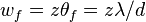
For a slit, the angular distance from the center of the central maximum to the first minimum is
 .
For a circular opening, the angular distance from the center of the central maximum to the first minimum is
If we look at two stars that have a large angular separation, their diffraction patterns hardly overlap, and we clearly distinguish that there are two stars.
The same would be true of two items of cell structure when viewed through a microscope.
As the two objects come closer, their diffraction patterns overlap and it may become difficult to distinguish the two images.
"Rayleigh's criterion" for the resolution of two point sources is that the first minimum of one diffraction pattern occurs at the central maximum of the other one.
Untrained eyes will loose distinction before this and well trained eyes may distinguish two sources even closer than Rayleigh's criterion.
DIFFRACTION AND FOURIER OPTICS PDF
Physical Optics. Diffraction. PDF


Fraunhofer diffraction by a single slit

This is an attempt to more clearly visualize the nature of single slit diffraction. The phenomenon of diffraction involves the spreading out of waves past openings which are on the order of the wavelength of the wave. The spreading of the waves into the area of the geometrical shadow can be modeled by considering small elements of the wavefront in the slit and treating them like point sources.
If light from symmetric elements near each edge of the slit travels to the centerline of the slit, as indicated by rays 1 and 2 above, their light arrives in phase and experiences constructive interference. Light from other element pairs symmetric to the centerline also arrive in phase. Although there is a progressive change in phase as you choose element pairs closer to the centerline, this center position is nevertheless the most favorable location for constructive interference of light from the entire slit and has the highest light intensity.
The first minimum in intensity for the light through a single slit can be visualized in terms of rays 3 and 4. An element at one edge of the slit and one just past the centerline are chosen, and the condition for minimum light intensity is that light from these two elements arrive 180° out of phase, or a half wavelength different in pathlength. If those two elements suffer destructive interference, then choosing additional pairs of identical spacing which progress downward across the slit will give destructive interference for all those pairs and therefore an overall minimum in light intensity.
One of the characteristics of single slit diffraction is that a narrower slit will give a wider diffraction pattern as illustrated below, which seems somewhat counter-intuitive. One way to visualize it is to consider that rays 3 and 4 must reach one half wavelength difference in light pathlength, and if the slit is narrower, it will take a greater angle of the rays to achieve that difference.


he diffraction patterns were taken with a
 helium-neon laser and a narrow single slit. The slit widths used were on the order of 100 micrometers, so their widths were 100 times the laser wavelength or more. A slit width equal to the wavelength of the laser light would spread the first minimum out to 90° so that no minima would be observed. The relationships between slit width and the minima and maxima of diffraction can be explored in thesingle slit calculation.

Diffraction and polarization of light
  • It is a common observation with the waves of all kind that they bend round the edge of an obstacle
  • Light like other waves also bends round corners but in comparison to sound waves small bending of light is due to very short wavelength of light which is of the order of 10-5
  • This effect of bending of beams round the corner was first discovered by grimed (Italy 1618-1663)
  • We now define diffraction of light as the phenomenon of bending of light waves around the corners and their spreading into the geometrical shadows
  • Fresnel then explained that the diffraction phenomenon was the result of mutual interference between the secondary wavelets from the same dif wave front
  • Thus we can explain diffraction phenomenon using Huygens�s principle
  • The diffraction phenomenon are usually divided into two classes

    i) Fresnel class of diffraction phenomenon where the source of light and screen are in general at a finite distance from the diffracting aperture

    ii) Fruanhofer class of diffraction phenomenon where the source and the screen are at infinite distance from the aperture, this is easily achieved by placing the source on the focal plane of a convex lens and placing screen on focal plane of another convex lens. This class of diffraction is simple to treat and easy to observe in practice
  • Here in this chapter we will only be considering fraunhofer class diffraction by a single slit

2. Fraunhofer Diffraction by single slit

  • Let us first consider a parallel beam of light incident normally on a slit AB of width 'a' which is of order of the wavelength of light as shown below in the figure


    Fraunhofer Diffraction by single slit 
  • A real image of diffraction pattern is formed on the screen with the help of converging lens placed in the path of the diffracted beam
  • All the rays that starts from slit AB in the same phase reinforce each other and produce brightness at point O on the axis of slit as they arrive there in the same phase
  • The intensity of diffracted beam will be different in different directions and there are some directories where there is no light
  • Thus diffraction pattern on screen consists of a central bright band and alternate dark and bright bands of decreasing intensity on both sides
  • Now consider a plane wave front PQ incident on the narrow slit AB. According to Huygens principle each point t on unblocked portion of wavefront PQ sends out secondary wavelets in all directions
  • Their combined effect at any distant point can be found y summing the numerous waves arriving there from the principle of superposition
  • Let C be the center of the slit AB.The secondary waves, from points equidistant from center C of the clit lying on portion CA and CB of wave front travel the same distance in reaching O and hence the path difference between them is zero
  • These waves reinforce each other and give rise to the central maximum at point O
  • i) Condition for minima
  • We now consider the intensity at point P1 above O on the screen where another set of rays diffracted at a angle θ have been bought to focus by the lens and contributions from different elements of the slits do not arise in phase at P1
  • If we drop a perpendicular from point A to the diffracted ray from B,then AE as shown in figure constitutes the diffracted wavefront and BE is the path difference between the rays from the two edges A and B of the slit.
  • Let us imagine this path difference to be equal to one wavelength.
  • The wavelets from different parts of the slit do not reach point P1 in the phase because they cover unequal distance in reaching P1.Thus they would interfere and cancel out each other effect. For this to occur

    BE=λ
    Since BE=ABsinθ
    asinθ=λ
    or sinθ=λ/a
    or θ=λ/a                         ---(1)
    As angle of diffraction is usually very small so that
    sinθ=θ
  • Such a point on screen as given by the equation (1) would be point of secondary minimum
  • It is because we have assume the slit to be divided into two parts, then wavelets from the corresponding points of the two halves of the slit will have path difference of #955;/2 and wavelets from two halves will reach point P1 on the screen in a opposite phase to produce minima
  • Again consider the point P2 in the figure 1 and if for this point path difference BE=2λ ,then we can imagine slit to be divided into four equal parts
  • The wavelets from the corresponding points of the two adjacent parts of the slit will have a path difference of λ/2 and will mutually interfere to cancel out each other
  • Thus a second minimum occurs at P2 in direction of θ given by
    θ=2θ/a
  • Similarly nth minimum at point Pn occurs in direction of θ given by
    θn=nθ/a                             ---(2)
  • ii) Positions of maxima
  • If there is any point on the screen for which path difference
    BN=asinθ=3θ/2
    Then point will be position of first secondary maxima
  • Here we imagine unblocked wavefront to be divided into three equal parts where the wavelets from the first two parts reach point P in opposite phase thereby cancelling the e effects of each other
  • The secondary waves from third part remain uncancelled and produce first maximum at the given point
  • we will get second secondary maximum for BN=5θ/2 and nth secondary maxima for 
    BN=(2n+1)θ/2 =asinθn                               ---(3)

    where n=1,2,3,4..
  • Intensity of these secondary maxima is much less then central maxima and falls off rapidly as move outwards
  • Figure below shows the variation of the intensity distribution with their distance from the center of the central maxima


    variation of the intensity distribution with their distance from the center of the central maxima

Diffraction by a slit of infinite depth[edit]


Graph and image of single-slit diffraction
The width of the slit is W. The Fraunhofer diffraction pattern is shown in the image together with a plot of the intensity vs. angle θ.[9] The pattern has maximum intensity at θ = 0, and a series of peaks of decreasing intensity. Most of the diffracted light falls between the first minima. The angle, α, subtended by these two minima is given by:[10]
 \alpha \approx {\frac{2 \lambda}{W}}
Thus, the smaller the aperture, the larger the angle, α subtended by the diffraction bands. The size of the central band at a distance z is given by
d_f = \frac {2 \lambda z}{W}
For example, when a slit of width 0.5 mm is illuminated by light of wavelength 0.6 µm, and viewed at a distance of 1000 mm, the width of the central band in the diffraction pattern is 2.4 mm.
The fringes extend to infinity in the y direction since the slit and illumination also extend to infinity.
If W < λ, the intensity of the diffracted light does not fall to zero, and if D << λ, the diffracted wave is cylindrical.

Fraunhofer diffraction - Single slit


The Fraunhofer diffraction due to a single slit is very easy to observe. An adjustable slit is placed on the table of a spectroscope and a monochromatic light source is viewed through it using the spectroscope telescope (see Figure 1(a)). An image of the slit is seen as shown in Figure 1(b). As the slit is narrowed a broad diffraction pattern spreads out either side of the slit, only disappearing when the width of the slit is equal to or less than one wavelength of the light used.
The diffraction at a single slit of width a is shown in Figure 2. Diffraction occurs in all directions to the right of the slit but we will just concentrate on one direction towards a point P in a direction θ to the original direction of the waves. Plane waves arrive at P due to diffraction at the slit AB. Waves coming from the two sides of the slit have a path difference BN and therefore interference results.

But BN = a sin(θ), and if this is equal to the wavelength of the light (λ) the light from the top of the slit and the bottom of the slit a will cancel out.and a minimum is observed at P. This is because if the path difference between the two extremes of the slit is exactly one wavelength there will be points in the upper and lower halves of the slit that will be half a wavelength out of phase.

Therefore the general condition for a minimum for a single slit is:

mλ = a sin θ
where m = 1, 2, 3, 4 and so on

The path difference between light from the top and bottom of the slit is written mλ where m is the number of wavelengths 'fitting into' BN. m is also known as the 'order' of the diffraction image.

If the intensity distribution for a single slit is plotted against distance from the slit, a graph similar to that shown that shown in Figure 3 will be obtained. The effect on the pattern of a change of wavelength is shown in Figure 4.

Wavelength effects

These two diagrams show the effect of a change of wavelength on the single slit diffraction pattern. The pattern for red light is broader than that for blue because of the longer wavelength of red light. 

Diffraction: Single slit


Diffraction: bending of light around the obstacles
Diffraction is a spreading of light around the edges of obstacles.
Diffraction is a manifestation of the wave nature of light
Clearest explanation of diffraction is using viewing wave propagation according to Huygen's principle: each point disturbed by the advancing wave front can be viewed as a source of a spherical wave, new front is enveloped of these secondary spherical wave fronts

We have already used Huygens principle to describe phenomenon of bending of the light ray on interface between media with different refractive index but it also tells that the light will propagate behind the obstacles - diffract

RefractionDiffraction


We have used diffraction before to create two coherent sources of light by a wave passing through two holes.
Diffraction and interference
Outcome of diffraction is not simple. Diffraction leads to intersecting rays of light, which are coherent and interfere.
Interference pattern formed by the diffracted light is called, for short diffraction pattern
Sometimes it is emphasized that we speak about diffraction picture when we consider interference from many sources - as for example continous distribution of sources between the barriers in the Figure above.
Note: Diffraction and interference are different phenomena (despite what textbook says :) )
Single slit diffraction
One of the most important examples of diffraction effects is the passage of light through a hole of finite size.
If light passes through narrow, point like hole, almost exact spherical wave forms. However if the hole has a finite size, an interference pattern forms behind the hole
We shall consider narrow (but finite width) slits, rather than round holes. The wavefronts that are formed by the slit are cyllindical rather than spherical
Single Slit Diffraction Applet
Note that the interference patern of diffracted light from a wide slit although has geometrical similarity to two narrow slits, is guite different from as far as intensity distribution is concerned (see for example much brighter central fringe)
We shall compute the distribution of the intensity at the screen beyond the slit.
The pattern near the slit, where exact wavefront profiles are important are called near-field, or Fresnel, diffraction . The pattern at the screen far away, where we can use geometrical optics rays and approximations we have done in intereference studies is called far-field, or Fraunhofer diffraction
We shall consider exclusively the far-field, Fraunhofer, diffraction pattern.
Intensity in Fraunhofer diffraction pattern from a single slit
I will replace several pages of discussion in the text book (but read them) which avoids mathematics with one line calculation using a simple integration.
Just to illustrate that often mastering advanced mathematics makes things easier - thats what for it is introduced in the first place, actually.
Resulting pattern is the sum of the waves from every point in a slit.

With continous distribution of source points, it is an integral over position of a point in a slit y If the center of a slit has the coordinate y = 0 and the width of the slit is a, then y varies from -a/2 to a/2
So we have for the amplitude

and, finally, for the intensity
Here is how it looks like
Minima of Intensity in Fraunhofer diffraction pattern from a single slit
This is simple, minima is achived at observation angles θ where sin(π(a/λ) sinθ) vanishes, i.esin(θmin) = ±m λ/a
but not for m = 0 , only for m = 1, 2 ...
The separation between minima widens when the wavelengths increases or the slit width decreases
This is why when slit is very narrow a ≈ 0 , the first minima is far away and one has continous distribution of light.
sinθ varies from -1 to 1 with zero achieved straight ahead of the slit. Thus, the number of minima observed isnmin = 2 int(a/λ)
If slit is narrower than the wavelength, a < λ, no minima are observed.
Maxima of Intensity in Fraunhofer diffraction pattern from a single slit
The main maxima of intensity is at θ = 0 (yes, zero divide by zero gives one here ! )
Because main maximum is where minimum is expected to be for m=0, it is twice wider than other maxima, occuping space between minima at ± λ/a . It's width in terms of sinθ is 2 λ/a
Positions of other maxima are only approximately halfway between the minimasin(θmax) ≈ ± (m + ½) λ/a
Depending on m we speak about first order (m=±1), second order (m=±2) etc. maxima
The approximate value of peak intensity at the maximum m > 0 is thenIm ≈ I0 / ( π2 (m + ½)2)

Fraunhofer Diffraction PDF FILE
Fraunhofer Diffraction PDF File


fraunhofer diffraction double slit

In the double-slit experiment, the two slits are illuminated by a single light beam. If the width of the slits is small enough (less than the wavelength of the light), the slits diffract the light into cylindrical waves. These two cylindrical wavefronts are superimposed, and the amplitude, and therefore the intensity, at any point in the combined wavefronts depends on both the magnitude and the phase of the two wavefronts.[15] These fringes are often known as Young's fringes.
The angular spacing of the fringes is given by
~\theta_f = \lambda /d
The spacing of the fringes at a distance z from the slits is given by [16]
~w_f=z \theta_f = z \lambda /d
where d is the separation of the slits.
The fringes in the picture were obtained using the yellow light from a sodium light (wavelength = 589 nm), with slits separated by 0.25 mm, and projected directly onto the image plane of a digital camera.
Double slit interference fringes can be observed by cutting two slits in a piece of card, illuminating with a laser pointer, and observing the diffracted light at a distance of 1 m. If the slit separation is 0.5 mm, and the wavelength of the laser is 600 nm the spacing of the fringes viewed at a distance of 1 m would be 1.2 mm.

Semi quantitative explanation of double-slit fringes[edit]

The difference in phase between the two waves is determined by the difference in the distance travelled by the two waves.
Geometry for far field fringes
If the viewing distance is large compared with the separation of the slits (the far field), the phase difference can be found using the geometry shown in the figure below right. The path difference between two waves travelling at an angle θ is given by:
d \sin \theta \approx d \theta
When the two waves are in phase, i.e. the path difference is equal to an integral number of wavelengths, the summed amplitude, and therefore the summed intensity is maximum, and when they are in anti-phase, i.e. the path difference is equal to half a wavelength, one and a half wavelengths, etc., then the two waves cancel and the summed intensity is zero. This effect is known as interference.
The interference fringe maxima occur at angles
~ d \theta_n = n \lambda,~ n=0,1,2.....
where λ is the wavelength of the light. The angular spacing of the fringes is θf is given by
 \theta _f \approx \lambda / d
When the distance between the slits and the viewing plane is z, the spacing of the fringes is equal to zθ and is the same as above:
~w = z\lambda / d
Image result for fraunhofer diffraction double slit
For two slits of width  separated by a distance , Fraunhofer diffraction gives the wavefunction
(1)
 (2)

where C is a constant, k is the wave number, and  is the angular distance from the center of the slit. The intensity pattern is then given by

The pattern formed by the interference and diffraction of coherent light is distinctly different for a single and double slit. The single slit intensity envelope is shown by the dashed line and that of the double slit for a particular wavelength and slit width is shown by the solid line. The photographs of the single and double slit patterns produced by a helium-neon laser show the qualitative differences between the patterns produced. You can see that the drawing is not to the same scale as the photographs, but the breaking up of the broad maxima of the single slit pattern into more closely spaced maxima is evident. The number of bright maxima within the central maximum of the single-slit pattern is influenced by the width of the slit and the separation of the double slits.

Three Slit Diffraction


Five Slit Diffraction

Under the Fraunhofer conditions, the light curve (intensity vs position) is obtained by multiplying the multiple slit interference expression times the single slit diffraction expression. The multiple slit arrangement is presumed to be constructed from a number of identical slits, each of which provides light distributed according to the single slit diffraction expression. The multiple slit interference typically involves smaller spatial dimensions, and therefore produces light and dark bands superimposed upon the single slit diffraction pattern.


(3)


The pattern formed by the interference and diffraction of coherent light is distinctly different for a single and double slit. The single slit intensity envelope is shown by the dashed line and that of the double slit for a particular wavelength and slit width is shown by the solid line. The photographs of the single and double slit patterns produced by a helium-neon laser show the qualitative differences between the patterns produced. You can see that the drawing is not to the same scale as the photographs, but the breaking up of the broad maxima of the single slit pattern into more closely spaced maxima is evident. The number of bright maxima within the central maximum of the single-slit pattern is influenced by the width of the slit and the separation of the double slits.

No comments:

Post a Comment

LOGIC GATES

LOGIC GATES: